Assembly instructions
The Bandolibre is meant to be built. It exists so that anyone, anywhere in the world, can make one if they want to — this page walks you through everything it takes.
If you take that journey, don’t be a stranger: let us know how it goes. We’d love to hear about your progress, see your build, and learn from what you discover along the way.
Don’t worry if a picture doesn’t quite match what you have in front of you: the photos were taken in a slightly different assembly order. The text is the reference.
Bill of material: Tools and consumables
Everything you need, down to the last washer — because nothing ruins a build like discovering, glue in hand, that the missing part ships from across the planet.
PCBs
| Part | Qty | Notes |
|---|---|---|
| Main PCB | 1 | EasyEDA design, Production files |
| Left wing PCB | 1 | idem |
| Right wing PCB | 1 | idem |
The production files are designed for economical two-layer assembly and were ordered from JLCPCB. Costs can be cut further by panelizing the designs into a single order.
Glue
| Part | Qty | Notes |
|---|---|---|
| Loctite 480 | 2 drops |
Bonds the magnet to the bellows blade spring. The magnet must not creep or peel, or the Hall reading drifts; and the bond sits on a blade that flexes on every stroke, so it must resist cyclic peel without cracking. 3M DP420 and Loctite EA 9466 are alternatives; all three are toughened (rubber-modified) structural adhesives that meet both.
Bellows spring blade
| Part | Qty | Notes |
|---|---|---|
| 65Mn spring steel strip, 1.2 × 40 × 300 mm | 1 | supplier |
The steel must be manganese-alloyed (65Mn) spring steel. Manganese gives it a wide elastic domain, so the blade flexes far on every bellows stroke and returns without taking a permanent set.
A 1.5 mm strip can be used instead for extra rigidity, but the bellows model must be adjusted to match the stiffer blade.
Magnets
| Part | Qty | Notes |
|---|---|---|
| Permanent magnet, 14.5 × 6 × 2 mm | 2 |
Bonded to the spring blade, the magnets move with it as it bends. A pair of Hall-effect sensors reads the resulting field change to measure the blade’s flexion, which gives the force the player applies to the bellows.
Cutting the blade springs
| Part | Qty | Notes |
|---|---|---|
| Angle grinder | 1 | 125 mm |
| Norton Extreme steel/inox cutting disc | 1 | 125 × 1.6 mm, for an angle grinder |
Cuts the spring steel to length. The disc is thin enough to keep the kerf narrow and the heat-affected zone small, so the steel keeps its temper at the cut edge.
Programming
| Part | Qty | Notes |
|---|---|---|
| ST-LINK V3 MINIE | 1 | preferred; or ST-LINK V3 SET |
| Tag-Connect TC2070-IDC-050 cable | 1 | 14 pogo pins that contact the board’s footprint directly with no mating connector |
| USB-B to USB-A cable | 1 | Powers the main board while programming, and carries MIDI to the host |
Chosen against a J-Link because it is fast, cheap, and free of licence restrictions. The ST-LINK V3 also exposes a USART, which is more robust than SWO for logging and lets you send commands to the firmware during development. The MINIE has all the features needed and is cheaper than the SET.
Hexagonal keys
| Part | Qty | Notes |
|---|---|---|
| Hexagonal Allen key H2 | 1 | |
| Hexagonal Allen key H2.5 | 1 | |
| Hexagonal Allen key H3 | 1 |
All screws can be fastened with these three hexagonal Allen keys.
PLA filament
| Part | Qty | Notes |
|---|---|---|
| PLA for the body | 850 g | Prusament PLA |
| PETG for the keys | 60 g | Prusament PETG |
Magnetic push buttons
| Part | Qty | Notes |
|---|---|---|
| Hall-effect switches | 71 | GATERON Low Profile Magnetic Jade HE |
You can opt for lighter 30±10gf springs selecting the non “Pro” version instead.
Screws
| Part | Qty | Notes |
|---|---|---|
| M4 × 30 socket head cap, stainless A2 | 4 | For the handles. supplier |
| M4 × 10 × 0.8 flat washer, stainless A2 | 4 | For the handles. supplier |
| M3 × 6 socket head cap, stainless A2 | 19 | For PCB fastening. supplier |
| M3 × 8 socket head cap, stainless A2 | 11 | For the main board blade clamp. supplier |
| M3 × 12 socket head cap, stainless A2 | 4 | For the wing blade clamp. supplier |
| M3 × 18 socket head cap, stainless A2 | 4 | For the main board enclosure. supplier |
| M3 × 5 flat head | 4 | For the handle straps. supplier |
Ribbon cable
| Part | Qty | Notes |
|---|---|---|
| IDC ribbon cable, FC 1.27 mm, 12P (2×6), 10 cm | 2 | supplier |
Connects each wing to the main board. IDC ribbon cable is available everywhere, and its 1.27 mm pitch keeps the connectors short. The 12 conductors give the SPI link spare pins for interleaved grounds (lower noise) and extra VCC lines (less voltage drop).
Step-by-step assembly
Print the parts
All the parts are printed with 15% density with no support.
The printable files are attached to the GitHub releases:
bandolibre-models-xxx.zip— STEP files exported from the Onshape model.xxxx - slice.3mf— PrusaSlicer projects that reference the models already arranged on the plate.
The projects print with “Complete individual objects” enabled, so each part is finished before the next one starts. This avoids the travel moves back and forth between parts, which makes the print faster and improves surface quality by keeping oozing and stringing off the finished parts.
| Part | Count | Material | Print time | Filament |
|---|---|---|---|---|
| Central body | 1 | PLA | 1 h 32 min | 40 g |
| Central body blade clamp | 1 | PLA | 0 h 37 min | 24 g |
| Right keyboard body | 1 | PLA | 5 h 50 min | 223 g |
| Right keyboard cover | 1 | PLA | 1 h 21 min | 58 g |
| Left keyboard body | 1 | PLA | 5 h 50 min | 225 g |
| Left keyboard cover | 1 | PLA | 1 h 21 min | 58 g |
| Left and right handles | 1 | PLA | 1 h 24 min | 62 g |
| Set of 24 keys | 3 | PETG | 2 h 10 min | 18 g |
| Total | 24 h 25 min | 744 g |
Cut the spring blade
With the angle grinder and slim cutting disc, cut the 65Mn spring steel strip to a 300 mm length.
Clamp the blade to a plank and keep a trickle of water running over the cut to carry away the heat. If the steel gets too hot it re-hardens (quenches) at the cut, losing the temper that gives it its elastic properties.
Assemble keyboards
- Push the keycaps onto the Gateron push-button switches.
- Lay out the components on the table: place the keyboard PCB on the ESD mat, with the switches and keycaps within reach. Double-check the connectors are covered with a protection to avoid bending the pins.
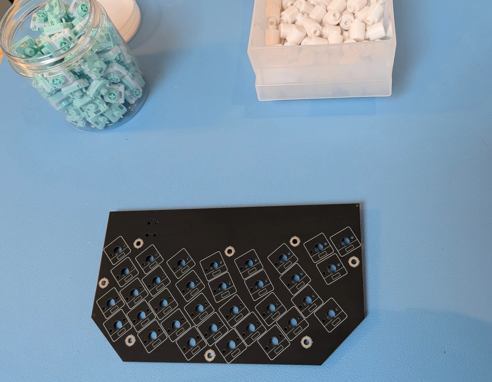
- Place the push buttons on the back of the board. Orient each one so the crystal aligns with the silkscreen drawing, so that the magnet sits in front of the sensor.
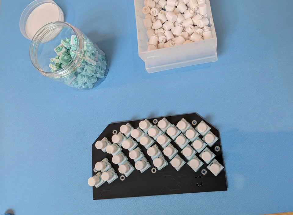
- Hold the board by its component side and bring the printed keyboard body down onto it, guiding every switch through its matching hole in one motion. Seat the board fully so each switch clears its hole and the keycaps stand proud of the front face.
Assemble the main board
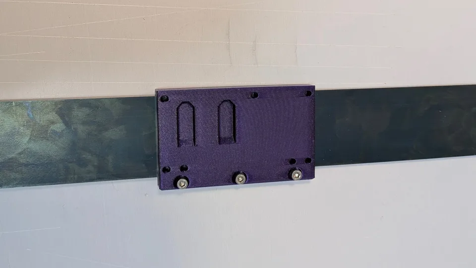
- Set the clamp at the exact midpoint of the 300 mm blade, so both free ends flex symmetrically under the bellows load.
- Fasten the clamp with 3 M3×8 screws.
- Find the magnet’s blade-facing polarity: press a spare Gateron switch to bring its internal magnet down against the bottom of the housing, then check which face of a bellows magnet that bottom attracts. That face goes against the blade.
- Fit the magnet guide, add a drop of glue to each seat, and set a magnet — attracted face down — into each. The guide aligns the magnet with its Hall sensor; the glue resists the cyclic peel of every bellows stroke.
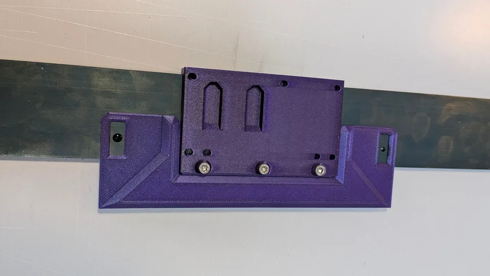
- Once the glue has cured, lift the magnet guide off the magnets.
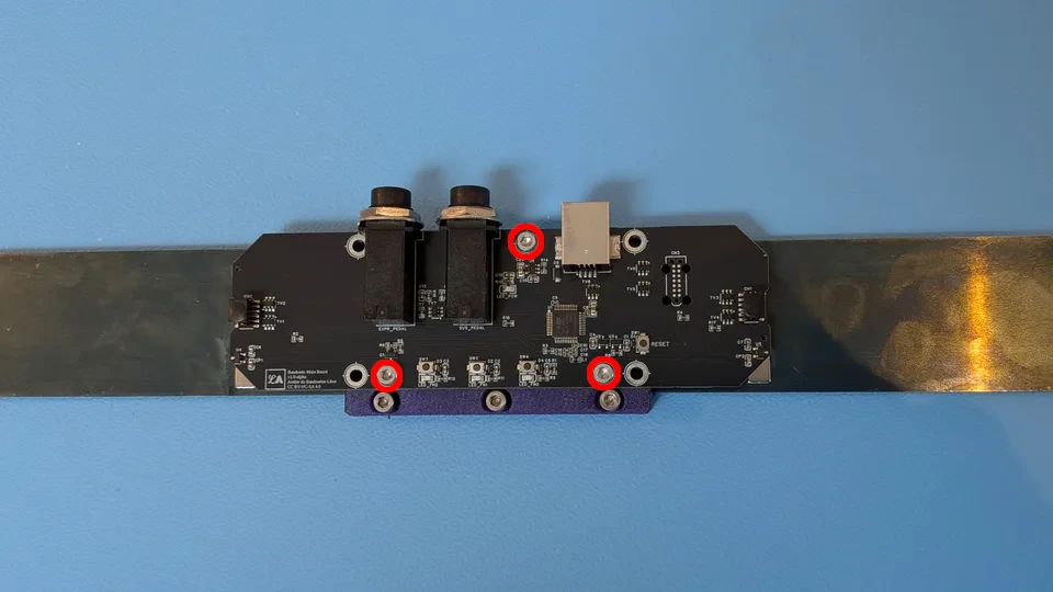
- Set the main board onto its support.
- Fasten it with 3 M3×6 screws.
Fit the handle straps
Velcro tape makes cheap adjustable handle straps.
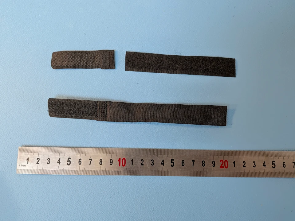
- Attach the velcro tape to each handle with two M3 × 5 flat head screws.
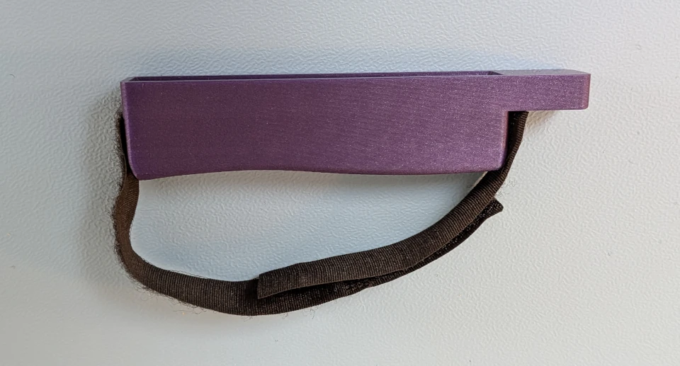
- Fix the left and right handles to their keyboards with two M4 × 30 socket head cap screws and washers each.
The handle position is adjustable; the median position matches the original instrument.
Fasten the wings to the blade
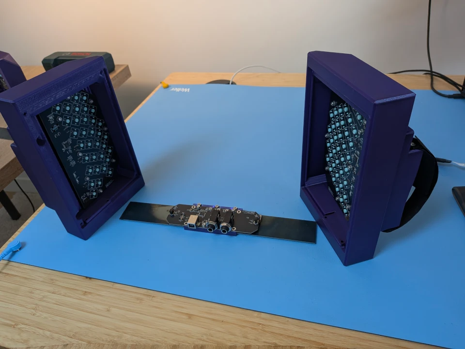
- Bring each assembled keyboard up to the blade and slide the blade into its wing clamp. The blade should be a snug fit.
- Fasten each clamp with two M3 × 12 screws.
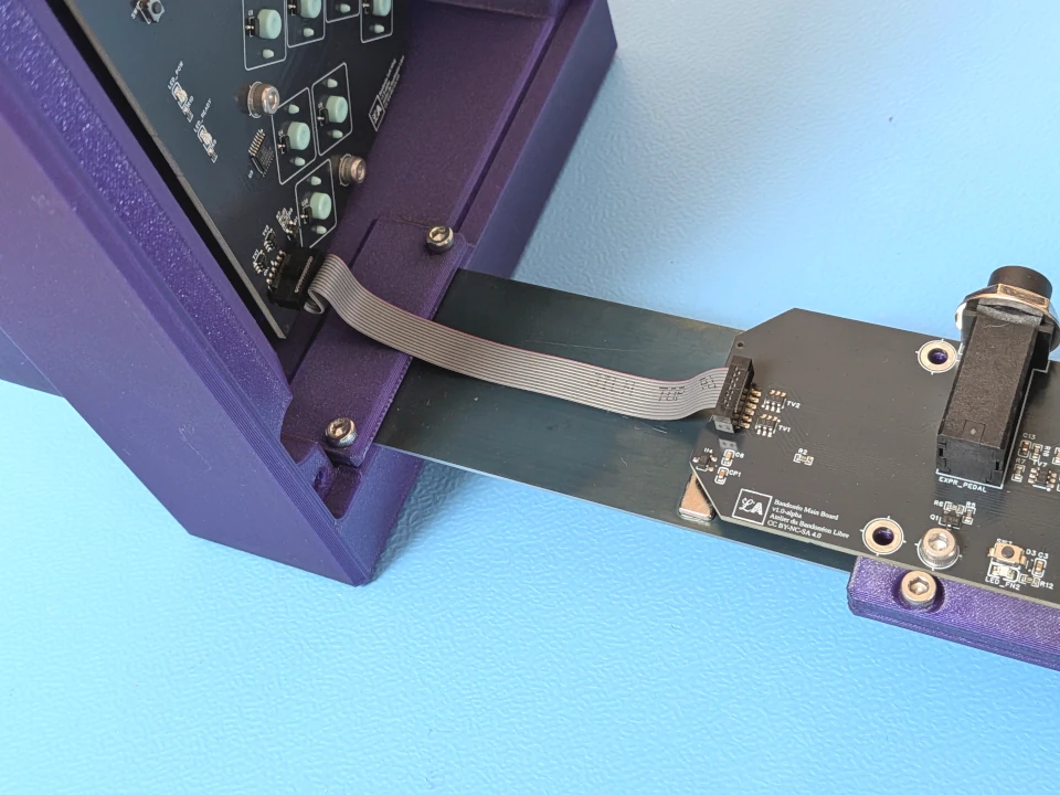
- Connect the IDC ribbon cables, keeping them flat and untwisted. The connectors are not keyed: the cable is symmetrical, so either end fits either board.
Program the main board
- Connect the main board to a USB port with the USB-B to USB-A cable. An orange power indicator lights up. The ST-LINK V3 can power the board on its own only while the wings are disconnected; now that everything is wired, the board must be powered over USB.
- Plug the TC2070-IDC-050 cable into the board footprint and into the ST-LINK V3, then connect the ST-LINK V3 to your workstation.
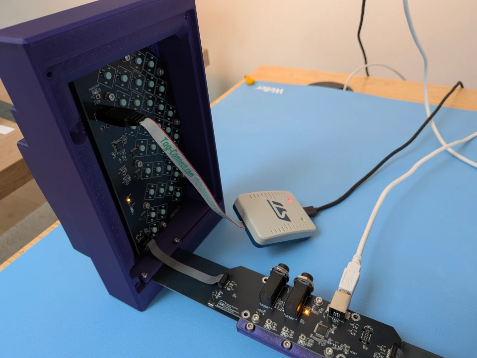
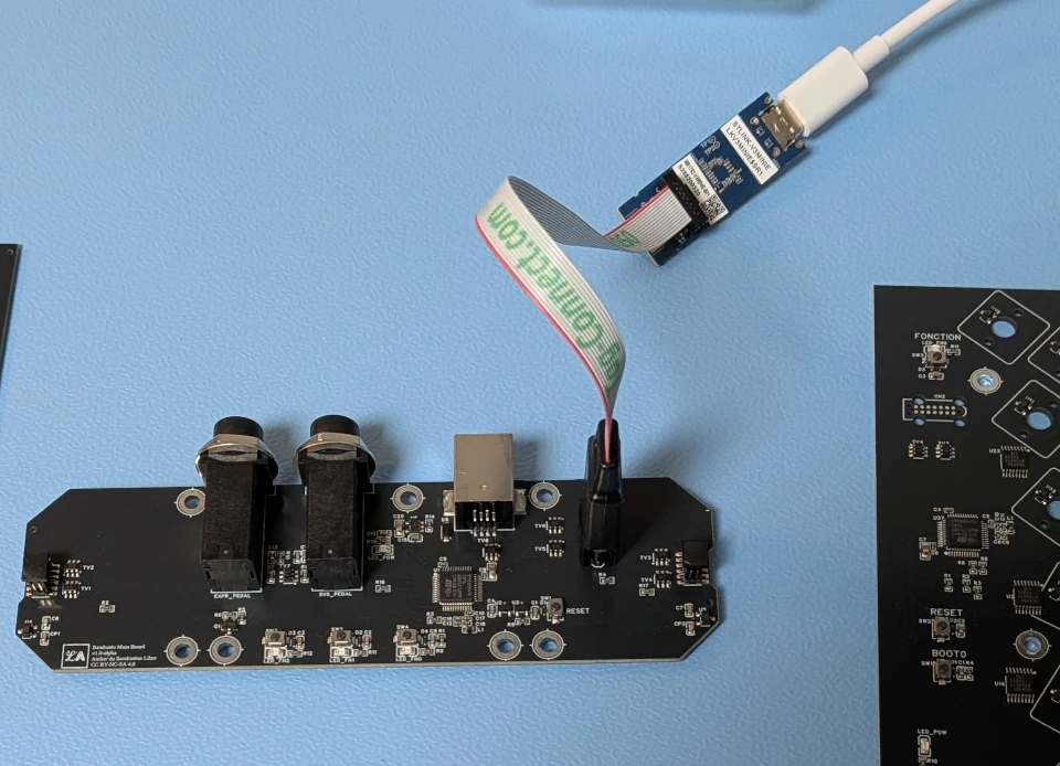
- Flash the board following Programming boards.
- Unplug the ST-LINK V3, then the USB cable.
Play and share
Your workstation should now detect the bandoneon as a USB MIDI device. Check that every key and both bellows sensors behave as intended before fitting the enclosure — everything is still accessible at this stage.
Then play it, and send us a picture of your build.